|
| |
Physics 3309 Homework 12
Chapter 10
10-9. Choosing the same coordinate system as in Example 10.3 (see Fig. 10-9), we see that the lateral deflection of the projectile is in the x direction and that the acceleration is
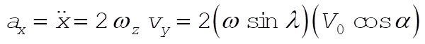 (1) (1)
Integrating this expression twice and using the initial conditions, 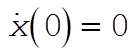 and and 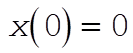 , we obtain , we obtain
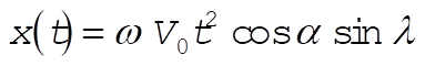 (2) (2)
Now, we treat the z motion of the projectile as if it were undisturbed by the Coriolis force. In this approximation, we have
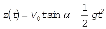 (3) (3)
from which the time T of impact is obtained by setting z = 0:
 (4) (4)
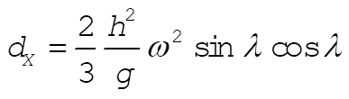
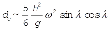
Substituting this value for T into (2), we find the lateral deflection at impact to be
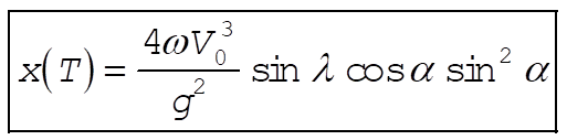 (5) (5)
10-13.
The small parameters which govern the approximations that need to be made to find the southerly deflection of a falling particle are:
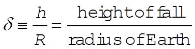 (1) (1)
and
 (2) (2)
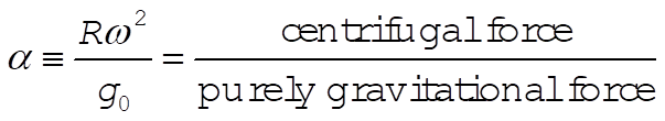
The purely gravitational component is defined the same as in Problem 10-12. Note that although both d and a are small, the product  is still of order is still of order  and therefore expected to contribute to the final answer. and therefore expected to contribute to the final answer.
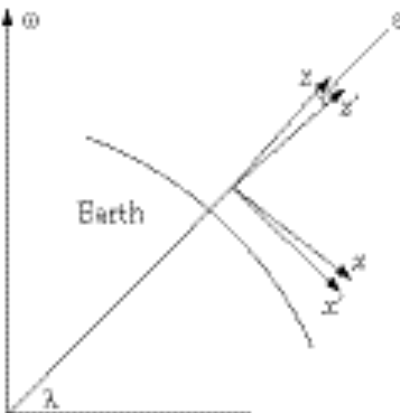
Since the plumb line, which defines our vertical direction, is not in the same direction as the outward radial from the Earth, we will use two coordinate systems to facilitate our analysis. The unprimed coordinates for the Northern Hemisphere-centric will have its x-axis towards the south, its y-axis towards the east, and its z-axis in the direction of the plumb line. The primed coordinates will share both its origin and its y¢-axis with its unprimed counterpart, with the z¢- and x¢-axes rotated to make the z¢-axis an outward radial (see figure). The rotation can be described mathematically by the transformation
 (3) (3)
 (4) (4)
 (5) (5)
where
 (6) (6)
as found from Problem 10-12.
a) The acceleration due to the Coriolis force is given by
 (7) (7)
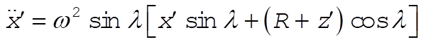
Since the angle between w and the z¢-axis is p – l, (7) is most appropriately calculated in the primed coordinates:
 (8) (8)
 (9) (9)
 (10) (10)
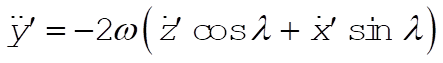
In the unprimed coordinates, the interesting component is
 (11) (11)
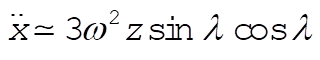
At our level approximation this becomes
 (12) (12)
Using the results for  and and  , which is correct to order w (also found from Example 10.3), , which is correct to order w (also found from Example 10.3),
 (13) (13)
Integrating twice and using the zeroth order result for the time-of-fall,  , we obtain for the deflection , we obtain for the deflection
 (14) (14)
b) The centrifugal force gives us an acceleration of
 (15) (15)
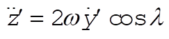
The component equations are then
 (16) (16)
 (17) (17)
 (18) (18)
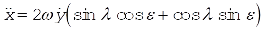
where we have included the pure gravitational component of force as well. Now transform to the unprimed coordinates and approximate
 (19) (19)
We can use Problem 10-12 to obtain sin e to our level of approximation
 (20) (20)
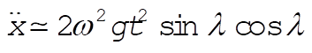
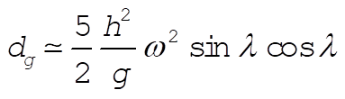
The prompts a cancellation in equation (19), which becomes simply
 (21) (21)
Using the zeroth order result for the height,  , and for the time-of-fall estimates the deflection due to the centrifugal force , and for the time-of-fall estimates the deflection due to the centrifugal force
 (22) (22)
c) Variation in gravity causes the acceleration
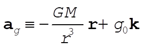 (23) (23)
where 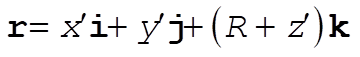 is the vector pointing to the particle from the center of the spherical Earth. Near the surface is the vector pointing to the particle from the center of the spherical Earth. Near the surface
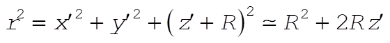 (24) (24)
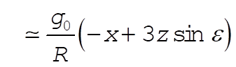
so that (23) becomes, with the help of the binomial theorem,
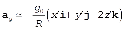 (25) (25)
Transform and get the x component
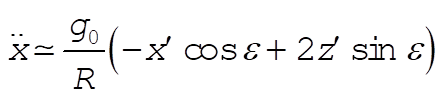 (26) (26)
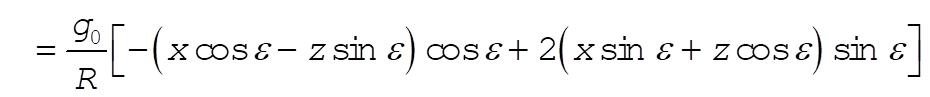 (27) (27)
 (28) (28)
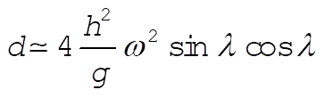
Using (20),
 (29) (29)
where we have neglected the  term. This is just thrice the part (b) result, term. This is just thrice the part (b) result,
 (30) (30)
Thus the total deflection, correct to order  , is , is
 (31) (31)
(The solution to this and the next problem follow a personal communication of Paul Stevenson, Rice University.)
Chapter 11
11-3. The equation of an ellipsoid is
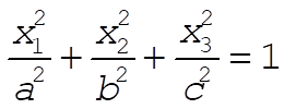 (1) (1)
which can be written in normalized form if we make the following substitutions:
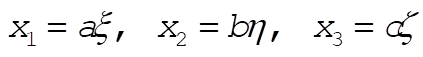 (2) (2)
Then, Eq. (1) reduces to
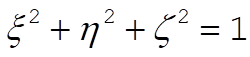 (3) (3)
This is the equation of a sphere in the (x,h,z) system.
If we denote by dv the volume element in the  system and by dt the volume element in the (x,h,z ) system, we notice that the volume of the ellipsoid is system and by dt the volume element in the (x,h,z ) system, we notice that the volume of the ellipsoid is
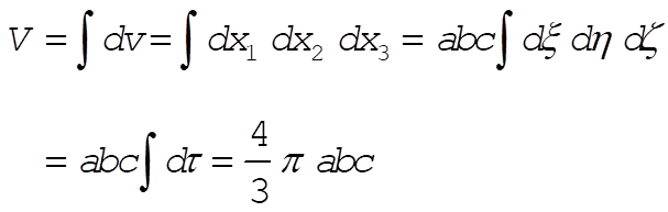 (4) (4)
because  is just the volume of a sphere of unit radius. is just the volume of a sphere of unit radius.
The rotational inertia with respect to the  passing through the center of mass of the ellipsoid (we assume the ellipsoid to be homogeneous), is given by passing through the center of mass of the ellipsoid (we assume the ellipsoid to be homogeneous), is given by
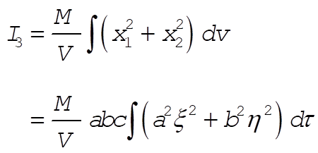 (5) (5)
In order to evaluate this integral, consider the following equivalent integral in which z = r cos q :
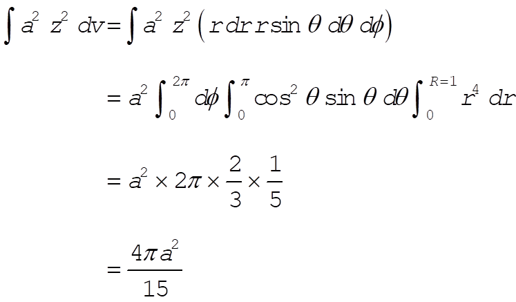 (6) (6)
Therefore,
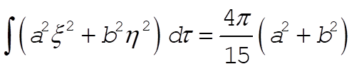 (7) (7)
and
 (8) (8)
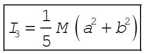
Since the same analysis can be applied for any axis, the other moments of inertia are
ĀĀĀĀĀĀĀĀĀĀĀĀĀĀĀĀĀĀĀĀĀĀĀĀĀĀ 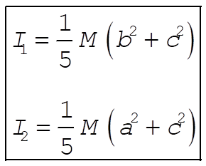 (9) (9)
ĀĀĀĀĀĀĀĀĀĀĀĀĀĀĀĀĀĀĀĀĀĀĀĀĀĀ 11-7.
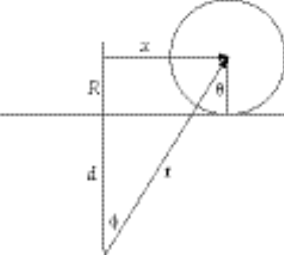
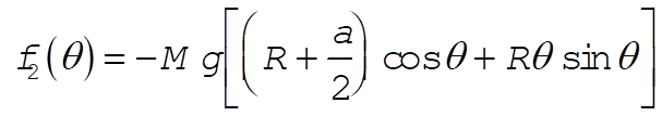
The force between the force center and the disk is, from the figure
 (1) (1)
Only the component along x does any work, so that the effective force is 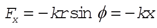 . This corresponds to a potential . This corresponds to a potential 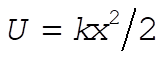 . The kinetic energy of the disk is . The kinetic energy of the disk is
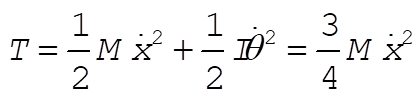 (2) (2)
where we use the result 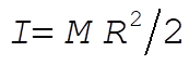 for a disk and dx = R dq. Lagrange’s equations give us for a disk and dx = R dq. Lagrange’s equations give us
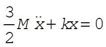 (3) (3)
This is simple harmonic motion about x = 0 with an angular frequency of oscillations
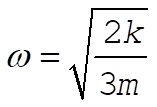 (4) (4)
ĀĀĀĀĀĀĀĀĀĀĀĀĀĀĀĀĀĀĀĀĀĀĀĀĀĀ 11-9.
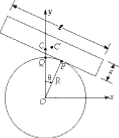
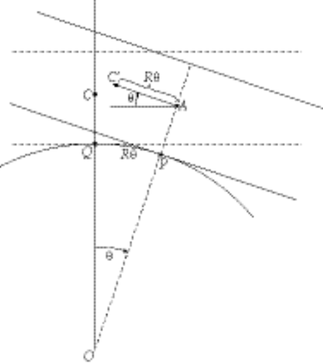
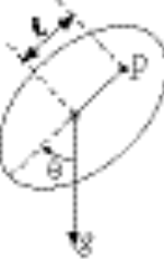
The diagram shows the slab rotated through an angle q from its equilibrium position. At equilibrium the contact point is Q and after rotation the contact point is P. At equilibrium the position of the center of mass of the slab is C and after rotation the position is C¢.
Because we are considering only small departures from q = 0, we can write
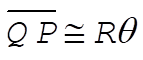 (1) (1)
Therefore, the coordinates of C¢ are (see enlarged diagram below)
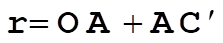 (2) (2)
so that
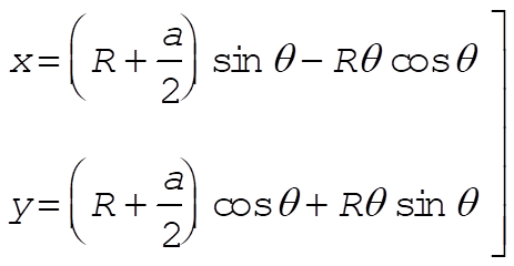 (3) (3)
Consequently,

from which
 (4) (4)
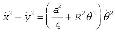
The kinetic energy is
 (5) (5)
where I is the moment of inertia of the slab with respect to an axis passing through the center of mass and parallel to the z-axis:
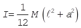 (6) (6)
Therefore,
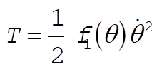 (7) (7)
where
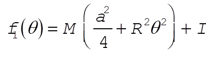 (8) (8)
The potential energy is
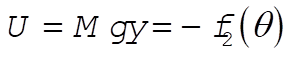 (9) (9)
where
 (10) (10)
and where Eq. (3) has been used for y.
The Lagrangian is
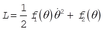 (11) (11)
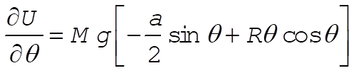
The Lagrange equation for q is
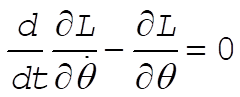 (12) (12)
Now,
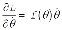
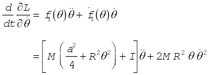 (13) (13)
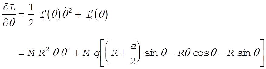 (14) (14)
Combining, we find
 (15) (15)
For the case of small oscillations,  and and  , so that Eq. (15) reduces to , so that Eq. (15) reduces to
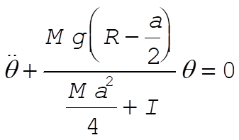 (16) (16)
The system is stable for oscillations around q = 0 only if
 (17) (17)
This condition is satisfied if 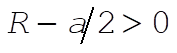 , i.e., , i.e.,
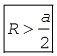 (18) (18)
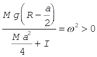
Then, the frequency is
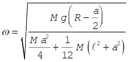 (19) (19)
Simplifying, we have
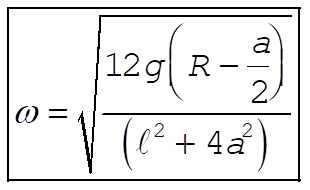 (20) (20)
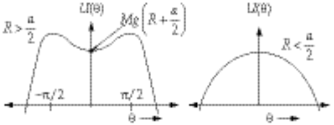
According to Eqs. (9) and (10), the potential energy is
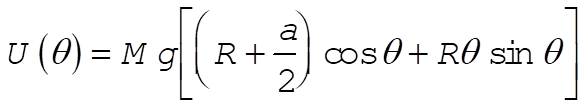 (21) (21)
This function has the following forms for  and and  : :
To verify that a stable condition exists only for  , we need to evaluate , we need to evaluate  at q = 0: at q = 0:
 (22) (22)
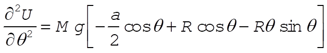 (23) (23)
and
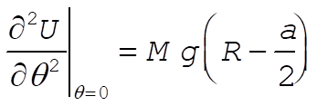 (24) (24)
so that
ĀĀĀĀĀĀĀĀĀĀĀĀĀĀĀĀĀĀĀĀĀĀĀĀĀĀ 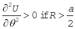 (25) (25)
ĀĀĀĀĀĀĀĀĀĀĀĀĀĀĀĀĀĀĀĀĀĀĀĀĀĀ 11-15.
We suspend the pendulum from a point P which is a distance l from the center of mass. The rotational inertia with respect to an axis through P is
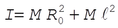 (1) (1)
where  is the radius of gyration about the center of mass. Then, the Lagrangian of the system is is the radius of gyration about the center of mass. Then, the Lagrangian of the system is
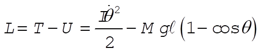 (2) (2)
Lagrange’s equation for q gives
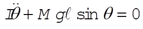 (3) (3)
For small oscillation,  . Then, . Then,
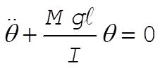 (4) (4)
or,
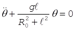 (5) (5)
from which the period of oscillation is
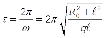 (6) (6)
If we locate another point P¢ which is a distance l¢ from the center of mass such that the period of oscillation is also t, we can write
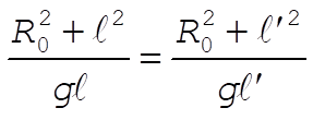 (7) (7)
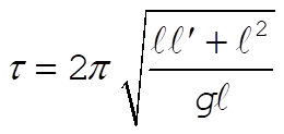
from which 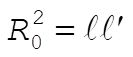 . Then, the period must be . Then, the period must be
 (8) (8)
or,
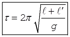 (9) (9)
This is the same as the period of a simple pendulum of the length l + l¢. Using this method, one does not have to measure the rotational inertia of the pendulum used; nor is one faced with the problem of approximating a simple pendulum physically. On the other hand, it is necessary to locate the two points for which t is the same.
ĀĀĀĀĀĀĀĀĀĀĀĀĀĀĀĀĀĀĀĀĀĀĀĀĀĀ 11-17.
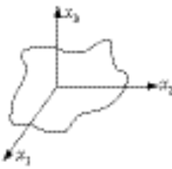
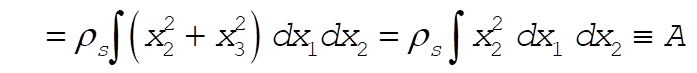
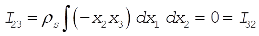
The plate is assumed to have negligible thickness and the mass per unit area is  . Then, the inertia tensor elements are . Then, the inertia tensor elements are
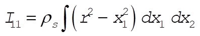
 (1) (1)
 (2) (2)
 (3) (3)
Defining A and B as above,  becomes becomes
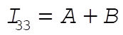 (4) (4)
Also,
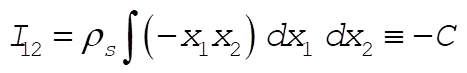 (5) (5)
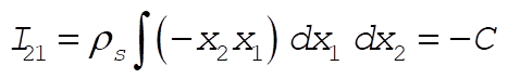 (6) (6)
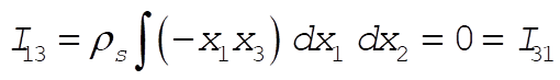 (7) (7)
 (8) (8)
Therefore, the inertia tensor has the form
ĀĀĀĀĀĀĀĀĀĀĀĀĀĀĀĀĀĀĀĀĀĀĀĀĀĀ 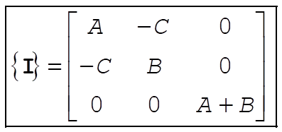 (9) (9)
11-23. We have
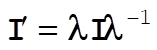 (1) (1)
Then,
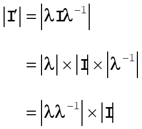
so that,
 (2) (2)
This result is easy to verify for the various examples involving the cube.
At this point, you can go to the 3309 page,
the UH Space Physics Group
Web Site, or my personal Home Page.
Edgar A. Bering, III , <eabering@uh.edu>
|
 Homework 12